| GENERAL DESCRIPTION |
 This broadband series of antenna is designed for medium to long range transmission or receiving applications.
| TECHNICAL SPECIFICATIONS | ||||
| MODEL | ANV45F | ANV120F | ||
| Electrical | ||||
| Frequency Range | (MHz) | 2 - 30 | ||
| Polarization | Horizontal | |||
| Power Rating-Average | Optional to 1 kW | |||
| VSWR | Typically less than 2:1, Max. 2.5:1 | |||
| Connector | "N" Socket | |||
| Mechanical | ||||
| Mast Height | rear | (m) | 16 | 20 |
| front | (m) | 4 | 4 | |
| Mast Guy Radius | rear | (m) | 10 | 10 |
| front | (m) | 3 | 3 | |
| Ground Dimensions | vee length | (m) | 35.5 | 106 |
| vee width | (m) | 50 | 88 | |
| Wind Rating | 160 km/hr | |||
| Specifications may change without notice | ||||
| AZIMUTH RADIATION PATTERNS | |
| ANV45F | ANV120F |
|
|
| ELEVATION RADIATION PATTERNS | |
| ANV45F | ANV120F |
 |
 |
| GAIN | |
| ANV45F | ANV120F |
 |
 |
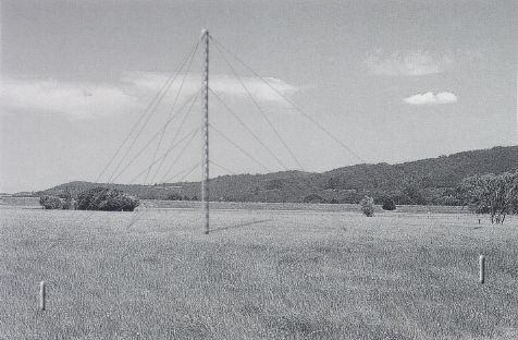
| ANTENNA PICTURE |
 |
| ORDERING INFORMATION | ||||||
| Example | Model | Input Power | Always 0 | Always 0 | ||
| ANV45F*100 | ANV45F | * | 1 | 0 | 0 | |
| 1 | 150 W Average | |||||
| 2 | 1 kW Average | |||||